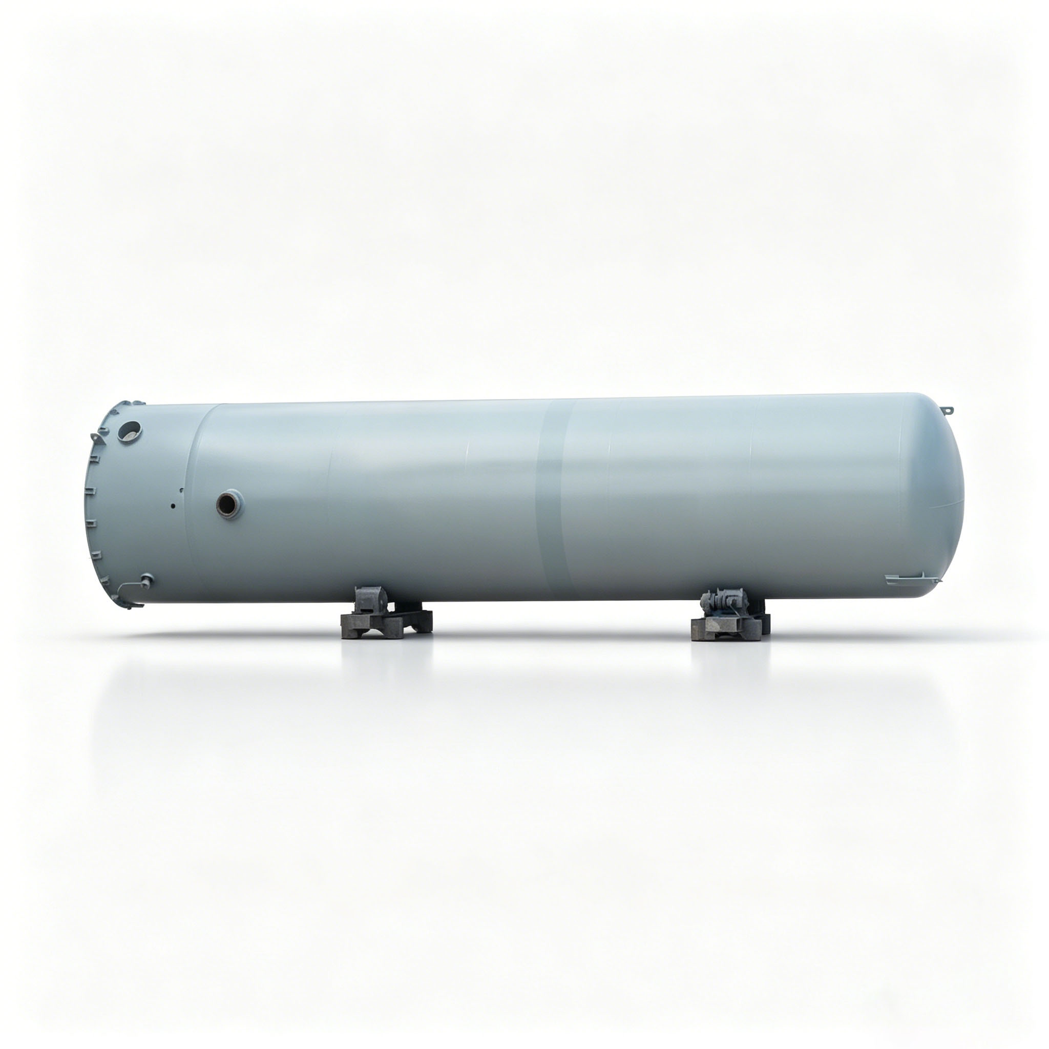
In industrial Pressure Swing Adsorption (PSA) hydrogen‑generation facilities, many on‑site stability issues — such as control‑valve hunting, compressor surge, pipeline pressure oscillation and false interlock trips — can be traced back to the inherent periodic pulsation characteristics of PSA units. The PSA hydrogen buffer tank acts as a critical piece of equipment bridging the PSA hydrogen‑producing section and downstream consumer systems. Frequently underestimated in engineering designs, it is an “invisible core component” that largely governs overall system stability.
This article walks through the root cause of PSA‑induced pressure pulsation, the engineering value of hydrogen buffer tanks, placement principles, volume‑sizing methodology, safety specifications, structural‑material considerations and operation‑maintenance best practices. It explains how to properly specify and deploy a PSA hydrogen buffer tank and avoid turning it into an ineffective ornamental vessel.

1. Root Cause: Why PSA Hydrogen Generation Naturally Creates Pressure Pulsations
PSA hydrogen production relies on multi‑column cyclic sequencing: adsorption, pressure equalization, desorption and regeneration. This working principle makes it impossible to maintain perfectly constant outlet hydrogen flow and pressure.
During adsorption phases, stable hydrogen output pushes flow and pressure upward. During tower‑switching, equalization and desorption‑regeneration transients, hydrogen supply drops momentarily, generating pressure spikes and dips. These periodic flow‑pressure pulsations are intrinsic to PSA technology and cannot be fully eliminated solely by tuning valve logic or control systems.
Without adequate buffering upstream of downstream equipment, pulsations propagate through the whole system. Consequences include frequent control‑valve cycling, regulator oscillation, unstable compressor suction conditions, downstream pressure collapse, emergency interlock triggers and combustible‑gas alarms, threatening continuous‑process availability.
2. Engineering Value of PSA Hydrogen Buffer Tanks
The PSA hydrogen buffer tank is installed between the PSA outlet and downstream compression/purification/hydrogen pipeline networks, functioning as the primary pressure‑stabilization node. Its core purpose is not simple gas storage. Instead, it leverages the gas‑phase elasticity of the vessel volume to isolate periodic supply‑side disturbances from PSA and deliver a smooth, predictable pressure‑flow operating window for downstream equipment.
Two typical application scenarios are distinguished:
2.1 Upstream of Hydrogen Compressors
The buffer tank serves as a stabilizer for compressor inlet conditions. It suppresses cyclic suction‑pressure swings, mitigates surge risk, reduces frequent start‑stop and load‑unload cycles, lowers equipment fatigue, extends compressor service life and improves overall system energy efficiency.
2.2 Upstream of User Pipeline Networks / Multiple Parallel Consumers
The tank provides peak‑flow compensation and short‑fall supplementation. When consumer demand surges abruptly, stored hydrogen releases rapidly to sustain pipeline pressure. During PSA tower‑switching transients with momentary production reduction, the tank bridges the supply gap and prevents pressure collapse for parallel‑connected end‑users.
Product reference: PSA Hydrogen Buffer Tank

3. Volume Sizing: Reject “Bigger‑is‑Better” — Adopt Physics‑Driven Sizing Logic
A common engineering misconception is that larger tanks always deliver better stabilization. In reality, volume selection shall follow the logic: fluctuation source – allowable pressure deviation – response window, instead of empirical guesswork.
Before sizing, define critical boundary conditions: PSA cycle duration, switching frequency, native outlet‑pressure fluctuation band, instantaneous peak flow, allowable downstream pressure drop and control‑system response time. Missing these parameters yields guess‑based volume selection and high risk of poor field performance after commissioning.
Two categories of PSA‑originated disturbances must be addressed:
3.1 Low‑Frequency Periodic Fluctuations
These are synchronized with PSA tower‑switching cycles. Sufficient gas‑phase elasticity (allowable pressure swing multiplied by effective gas volume) inside the tank is required to damp these oscillations. For processes requiring high‑grade pressure stability (precision reduction reactions, fuel‑cell hydrogen supply, high‑purity process hydrogen), tighter allowable pressure tolerance demands larger effective gas volume.
3.2 Transient Pressure Spikes
Spikes stem from fast‑valve actuation, pressure‑equalization transients and momentary reverse flow. Sufficient transient throughput capacity of the tank and inlet piping is necessary to absorb or release gas rapidly. If downstream control loops respond slowly with narrow control bandwidth or tight interlock thresholds, a larger buffer time‑constant is required to attenuate disturbance amplitude.
Oversized tanks bring notable downsides: slow system dynamic response, pressure‑regulation lag and possible low‑frequency slow oscillation under improper sequencing. Larger dead‑gas volume also increases purge‑and‑commissioning gas consumption and time overhead. In case of contamination or accidental air ingress, recovery duration increases significantly.
Sizing target: satisfy the downstream stability window with reasonable engineering margin without unnecessarily inflating dead‑volume. Validate pressure‑swing amplitude with PSA operating data or process‑simulation curves during proposal‑phase engineering.

4. Pressure Rating & Safety Design: Design for Transient Worst‑Case Conditions
Pressure‑class definition and safety‑accessory configuration shall not rely merely on steady‑state operating pressure; transient worst‑case scenarios must be fully evaluated.
During PSA equalization, regeneration or abnormal switching sequences, short‑term pressure rises may occur. If design pressure and safety‑valve set‑point are too close to the normal‑fluctuation upper bound, frequent safety‑valve popping‑off will happen. This causes hydrogen loss, breaks the downstream stable‑pressure window and may trigger gas alarms or system shutdown.
Good‑practice requirements: maintain adequate margin between normal operating‑pressure envelope and safety‑valve activation range. Calculate safety‑valve back‑pressure effects and relief capacity to guarantee safe discharge under the most adverse transients. Relief outlets shall route to safe zones or dedicated recovery systems; avoid combustible‑gas accumulation near personnel‑occupied or dense‑equipment areas.
For indoor or semi‑enclosed installations, integrate ventilation capacity, combustible‑gas detection and emergency‑shut‑off interlocks into the overall design. Avoid afterthought‑style retrofits by simply adding standalone gas detectors.

5. Mechanical Design: Simplify Internals to Prevent Secondary Failures
PSA hydrogen buffer tanks function as gas‑phase‑only buffer vessels. The design principle is simple internals, low flow resistance and zero dead‑retention zones.
Minimize internal fittings to avoid stagnant‑gas pockets and impurity accumulation. Optimize nozzle layout for well‑defined flow patterns. The inlet shall achieve “soft entry” through orientation and layout to reduce jet impingement, noise and local high‑velocity erosion. The outlet shall provide stable gas withdrawal and prevent direct inlet‑to‑outlet flow short‑circuiting for uniform tank‑gas replacement.
Important note: never use the buffer tank as a separator or filter. If PSA outlet carries adsorbent fines, dust or trace liquid droplets, install dedicated separation‑filtration equipment upstream. Using the buffer tank for crude separation leads to internal solids accumulation, persistent contamination, valve‑seal degradation and higher maintenance risk.
Drain and vent nozzles shall enable full draining, isolation capability and safe depressurization. Define media destination and formal operating procedures for maintenance, purging and emergency scenarios.
6. Material & Fabrication: Resist Hydrogen Permeation and Cyclic‑Load Fatigue
Hydrogen has small molecular size and high‑permeation potential, imposing strict requirements on welding quality and sealing performance. Repeated PSA‑originated pressure swings subject buffer tanks to cyclic‑alternating loads. Even with moderate swing amplitude, numerous cycles create long‑term fatigue risks at welds and stress‑concentration locations.
Key fabrication‑control points:
- Strict quality control for shell butt‑welds and nozzle‑to‑shell joints. Apply complete non‑destructive‑testing programs plus gas‑tightness validation to eliminate micro‑cracks and leakage risks.
- For high‑pressure or high‑reliability projects, verify material selection, welding‑procedure qualification and heat‑treatment schemes against project specifications to accommodate long‑term pressure‑temperature cycling.
- Optimize reinforcement at openings and smooth structural transitions; eliminate sharp corners and abrupt stiffness changes to mitigate fatigue‑susceptible zones.

7. Instrumentation & Control: Prevent Coupled Oscillation via Loop‑Bandwidth Matching
Many field‑observed “pressure‑unstable” symptoms are not caused by insufficient tank volume, but by mismatched control bandwidth and response windows. Instrumentation and control logic aim at trend diagnosis, fault‑source identification and closed‑loop interlock coordination.
Instrument‑recommendations: combine local pressure gauge plus remote pressure transmitter to monitor fluctuation amplitude, frequency and abnormal spikes. Add temperature measurements to distinguish thermal‑originated pressure changes versus hydrodynamic disturbances. Deploy flow‑signal and valve‑position feedback as required to discriminate whether disturbances originate from upstream PSA production or downstream‑user load variations.
Control‑logic guidance: when feeding compressors downstream, coordinate compressor start‑stop / load‑unload logic with tank‑pressure operating windows to prevent frequent compressor cycling near pressure thresholds. For pipeline‑supply applications, align the buffer‑tank pressure window with downstream regulator control bandwidth. Avoid control‑loop coupling oscillation caused by “slow upstream buffering + fast downstream regulation”, a common root cause of “the harder you tune, the worse it gets”.
8. Commissioning & Operation‑Maintenance: Standardized Workflow for Closed‑Loop Management
Well‑executed design must be paired with standardized commissioning and maintenance procedures to sustain buffering performance. For first‑time commissioning or post‑maintenance restart: complete gas‑tightness inspection, valve‑position verification, interlock‑logic testing and alarm‑calibration. Observe process‑trend data for a period before full‑load grid‑connection; avoid direct full‑load energization without validation.
During routine operation, monitor pressure‑fluctuation trends. Gradually‑growing swing amplitude may indicate abnormal PSA cycle timing, sticking switching valves, intensified downstream‑load variation or incremental micro‑leakage. Frequent unexpected pressure spikes require investigation of equalization‑valve / switching‑valve logic and piping‑resistance changes. Periodically review historical trend data to accelerate fault‑diagnosis and improve overall system stability.

9. Conclusion — Turn the Buffer Tank Into a Solution‑Oriented Asset
The PSA hydrogen buffer tank is far more than an auxiliary accessory. It is core engineering hardware to suppress production‑side pulsations, stabilize downstream operating conditions and secure long‑run system safety.
Its core value lies in disturbance isolation and pressure‑flow conditioning rather than bulk‑gas storage. It keeps PSA‑induced periodic perturbations upstream and delivers stable operating conditions for compressors, pipelines and process consumers.
Only with properly‑executed volume‑sizing, transient‑safety‑boundary definition, robust mechanical‑material design, coordinated control‑loop configuration and standardized O&M workflows can the buffer tank solve root‑cause pulsation‑related problems instead of becoming a decorative pressure vessel.
For customizable equipment solutions, visit: PSA Hydrogen Buffer Tank