You can get the systematic engineering design of buried LPG tanks, detailing the holistic coordination of civil construction, corrosion protection, and maintenance accessibility required for long-term lifecycle management from this article
Technical Overview and Application Scenarios
Mounded/buried liquefied petroleum gas (LPG) storage tanks are primarily utilized for the underground storage and pressure-stabilizing buffering of LPG (predominantly propane, butane, and their mixtures). This equipment is widely applied in scenarios such as autogas refueling stations, cylinder filling stations, centralized industrial gas supply systems, and peak-shaving reserves. It is particularly suitable for projects requiring a minimized ground footprint and an elevated equipment protection rating.
Compared to aboveground storage tanks, buried tanks leverage the soil backfill cover to achieve a more stable operating ambient temperature and superior external protection capabilities while delivering identical storage and gas supply functions. This configuration effectively mitigates the impact of solar radiation and wind loads, significantly reducing the direct impact and hazards of external mechanical impacts, open flames, and thermal radiation on the tank shell.
Selecting an underground engineering scheme is not merely based on the simplistic assumption that “underground is safer”; rather, it constitutes a systematic engineering design. It requires the holistic coordination of core elements—including civil construction, corrosion protection, maintenance accessibility, site drainage, and emergency response—to ensure that the long-term operation of the storage tank remains controllable, inspectable, and maintainable.

System Process and Buffer Logic
In conventional gas supply systems, the buried LPG storage tank serves as the core storage and buffering unit. Upstream, the equipment is replenished via road tanker unloading or pipeline transfer. Downstream, it delivers the liquid-phase medium to vaporization units or user piping networks via pumping or self-pressure, or alternatively, supplies gas directly after vaporization and pressure stabilization.
Downstream gas consumption loads commonly exhibit peak-to-valley fluctuations, including refueling peaks, industrial gas consumption variances, and equipment startup/shutdown transients. Without a dedicated storage and buffer unit, problems such as gas supply pressure fluctuations, frequent pump cycling, and abrupt vaporizer load changes can easily be triggered.
Buried storage tanks provide adequate medium reserves and a stable source of gas supply, thereby achieving chronological decoupling among fluid replenishment, storage, and gas supply. This allows routine operations to be conducted in strict accordance with unloading windows, station operating procedures, and safety management systems, while reserving sufficient redundancy for emergency gas supply.

Media Characteristics and Safety Design
The core engineering design of buried LPG storage tanks is primarily governed by the characteristics of the LPG medium. LPG is a highly flammable and explosive medium that tends to form flammable gas clouds upon leakage and readily accumulates in low-lying areas. Furthermore, LPG is stored as a pressurized liquid; the tank pressure fluctuates dynamically with ambient temperature, and fluid transfer operations, temperature variations, and abnormal operating conditions will all induce pressure fluctuations.
Based on these characteristics, the storage tank system must be configured with a comprehensive pressure control and safety relief system. The overall layout of the station area must strictly implement regulatory requirements regarding safety separation distances, ventilation conditions, electrostatic grounding, lightning protection, and fire/explosion hazardous area classification.
An underground layout does not equate to a reduction in risk. Conversely, because the tank shell is concealed and leak detection is less immediate, it imposes more stringent requirements on engineering control. Design and operations must comprehensively optimize the entire chain of monitoring, inspection, and emergency response. This includes centralizing the valve manifold area to guarantee maintenance accessibility and inspection convenience, alongside integrating robust leak detection alarms and safety interlock strategies.
Structural Stress, Anti-Buoyancy, and Geotechnical Conditions
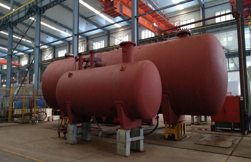
From a structural mechanics perspective, buried LPG storage tanks predominantly adopt a horizontal cylindrical pressure vessel configuration. The core configuration comprises the tank shell, saddle support structures, an integrated nozzle area within a valve pit/vault, safety appurtenances such as safety valves and emergency shut-off valves, as well as monitoring instruments for liquid level, pressure, and temperature.
The load cases for buried storage tanks are highly complex. In addition to internal design pressure, medium dead weight, and filling loads, the tank must withstand soil pressure, groundwater buoyancy, and backfill settlement forces. Concurrently, the impact of live loads transmitted by vehicles must be verified based on the layout of the station roadways.
In sites characterized by high groundwater tables or frequent rainy season water logging, buoyancy control is a critical imperative for design, construction, and mechanical acceptance. Anti-buoyancy measures—such as concrete deadweights, tie-down anchoring, or anti-buoyancy beams—must be deployed in conjunction with a robust drainage system to eliminate hazards such as nozzle cracking, valve pit damage, and stress concentration induced by tank flotation.
The quality of foundation engineering and backfilling directly dictates the service life of the equipment. Improper execution can lead to localized uneven stress on the tank body, which easily causes nozzle leakage, secondary welding stresses, and coating damage during long-term operation. Consequently, the control standards for tank foundation treatment, backfill material selection, and layered compaction techniques carry equal weight to the manufacturing quality of the tank itself.

External Anti-Corrosion and Cathodic Protection
External anti-corrosion and cathodic protection systems serve as the core assurance for the long-term stable operation of buried storage tanks. The underground soil environment is highly complex; factors such as moisture content, salinity, pH levels, stray currents, and soil resistivity can accelerate tank corrosion. Moreover, underground coating degradation and tank corrosion are highly concealed, making them difficult to detect prematurely.
Engineering practice widely adopts a composite protection scheme consisting of “external anti-corrosion coating encapsulation + cathodic protection + periodic inspection.” The external anti-corrosion coating serves as the primary barrier, while cathodic protection is utilized to suppress electrochemical corrosion at localized coating defects. Periodic potential testing and close interval potential surveys (CIPS) continuously verify the effectiveness of the protection.
The construction phase imposes rigorous demands on anti-corrosion workmanship. Strict quality control must be enforced regarding coating surface preparation, field joint coating/repair, adverse weather construction management, pre-backfill quality inspection, and full-process documentation. Backfilling must avoid sharp, hard objects that could scratch the coating, and sand bedding or protective layers should be added where necessary to mitigate the risk of mechanical damage.
For stations featuring complex stray currents and intricate grounding systems, the design phase must fully evaluate the operating conditions and implement electrical isolation and test station layouts to prevent the cathodic protection system from failing or becoming ineffective.
Valve Pit Design and Operation Accessibility
The design of the valve pit, valve vault, and nozzle area directly determines the operational convenience and maintainability of the buried LPG storage tank. The industry-standard practice is to centralize core valves and instruments—such as liquid inlets, liquid outlets, vapor balance lines, vent/recovery lines, safety valves, emergency shut-off valves, level gauges, and pressure gauges—within a valve pit or an aboveground valve manifold area.
The valve manifold area must concurrently satisfy protective requirements against rain, water ingress, freezing, liquid accumulation, and inadequate ventilation. Poor drainage within the valve pit accelerates valve corrosion and compromises maintenance safety; poor ventilation allows leaked flammable gases to accumulate, creating an explosive hazardous environment.
Therefore, the civil engineering design phase must concurrently integrate facilities such as valve pit drainage slopes, sump drainage pumps, pit cover sealing, and ventilation ducts. Gas detection and alarm interfaces must be reserved as required to ensure rapid troubleshooting of abnormal conditions during routine inspections.
Valves and instruments required for daily operation must prioritize operational accessibility and data visibility, thereby reducing the frequency of confined space entry into the pit and minimizing the exposure of O&M personnel to potential hazards.
Filling Operations and Automated Control
Storage tank filling and operations management must strictly align with filling ratios, temperature/pressure control standards, and safety protection logic. LPG exhibits a high coefficient of thermal expansion; if overfilled, the pressure inside the tank will surge drastically as the ambient temperature rises, which can easily trigger safety hazards such as frequent lifting of safety valves and equipment overpressure.
Engineering designs must establish a reasonable maximum filling limit based on medium composition, design pressure, station operating modes, and national codes, supported by precise liquid level monitoring and safety interlock control mechanisms.
During unloading operations, the vapor balancing pathway, emergency shut-off logic, electrostatic grounding specifications, and operational sequencing are directly tied to on-site safety and operational efficiency. Operations such as liquid/gas supply switching, pump startup/shutdown, and valve position management must be synergistically adapted to the equipment’s vaporization capacity and downstream pressure stabilization strategies to eliminate abnormal conditions such as pump cavitation (dry running), liquid hammer, and unscheduled venting.
For stations characterized by frequent startups and shutdowns, the conceptual design phase must target pressure stabilization, peak shaving, safety valve wear reduction, and the minimization of fugitive venting as core operational goals to inversely optimize valve manifold configurations and automated control strategies.
Manufacturing, Inspection, and Procurement Requirements
The manufacturing and inspection of buried LPG storage tanks must simultaneously satisfy general pressure vessel standards and specific underground operating condition requirements. It is essential to ensure that the tank structural strength and welding quality meet specifications, while optimizing external surface treatment, nozzle sealing, appurtenance compatibility, and on-site construction interface design to adapt to the underground environment.
During the design phase, material selection and corrosion allowance must be rationally determined based on design pressure, design temperature, medium characteristics, and operating conditions. Structural design and fabrication workmanship must be refined for stress-concentration zones such as nozzle attachment areas and saddle support regions.
Throughout the manufacturing process, critical operations—including material receiving inspection, welding procedure qualification (WPQ), non-destructive testing (NDT) of welds, hydrostatic pressure testing, and pneumatic tightness testing—must be stringently executed to guarantee reliable tank strength and sealing performance. Prior to ex-works delivery, external anti-corrosion coating application and quality acceptance must be finalized, and protective blanking/plugging for valves and instrument interfaces must be reinforced to prevent mechanical damage during transit.
During the equipment delivery acceptance and installation phases, emphasis must be placed on verifying nameplate parameters, manufacturer’s data books (MDB), external anti-corrosion integrity, nozzle orientations, and the valve manifold bill of materials (BOM). Concurrently, full-process quality control must be enforced regarding foundation dimensions, elevations, anti-buoyancy installations, backfill material types, and layered compaction quality, thereby preventing operational hazards arising from non-compliant installation despite the equipment meeting factory quality standards.
Conclusion and Pre-Project Engineering Interface
In summary, the selection and implementation of buried LPG storage tanks revolve around three core technical dimensions:
- Operating Condition Adaptation Logic: Determining unloading frequencies, peak-to-valley gas consumption regulation, and liquid/gas supply modes based on media characteristics and station types.
- Underground Risk Control: Addressing long-term hazards with emphasis on anti-buoyancy, settlement, site drainage, and valve pit safety.
- Equipment Asset Integrity and O&M: Ensuring long-term stable operations by relying on high-quality anti-corrosion coatings, cathodic protection, and routine inspection/monitoring.
During the pre-project engineering interface phase, it is recommended to define key technical data in advance, including:
- Medium composition and chemical analysis
- Design temperature and pressure parameters
- Gas consumption scale and peak/valley profiles
- Logistics unloading windows
- Site geotechnical and groundwater conditions
- On-site structural load standards
- Valve pit configuration types (e.g., concrete or steel)
- Monitoring and safety interlock requirements
Defining these parameters ensures precise alignment with storage tank volumes, structural parameters, nozzle configurations, anti-buoyancy designs, and anti-corrosion schemes. It also integrates critical construction and acceptance milestones into the project execution plan, minimizing post-commissioning failure risks.

