1. Operating Principle
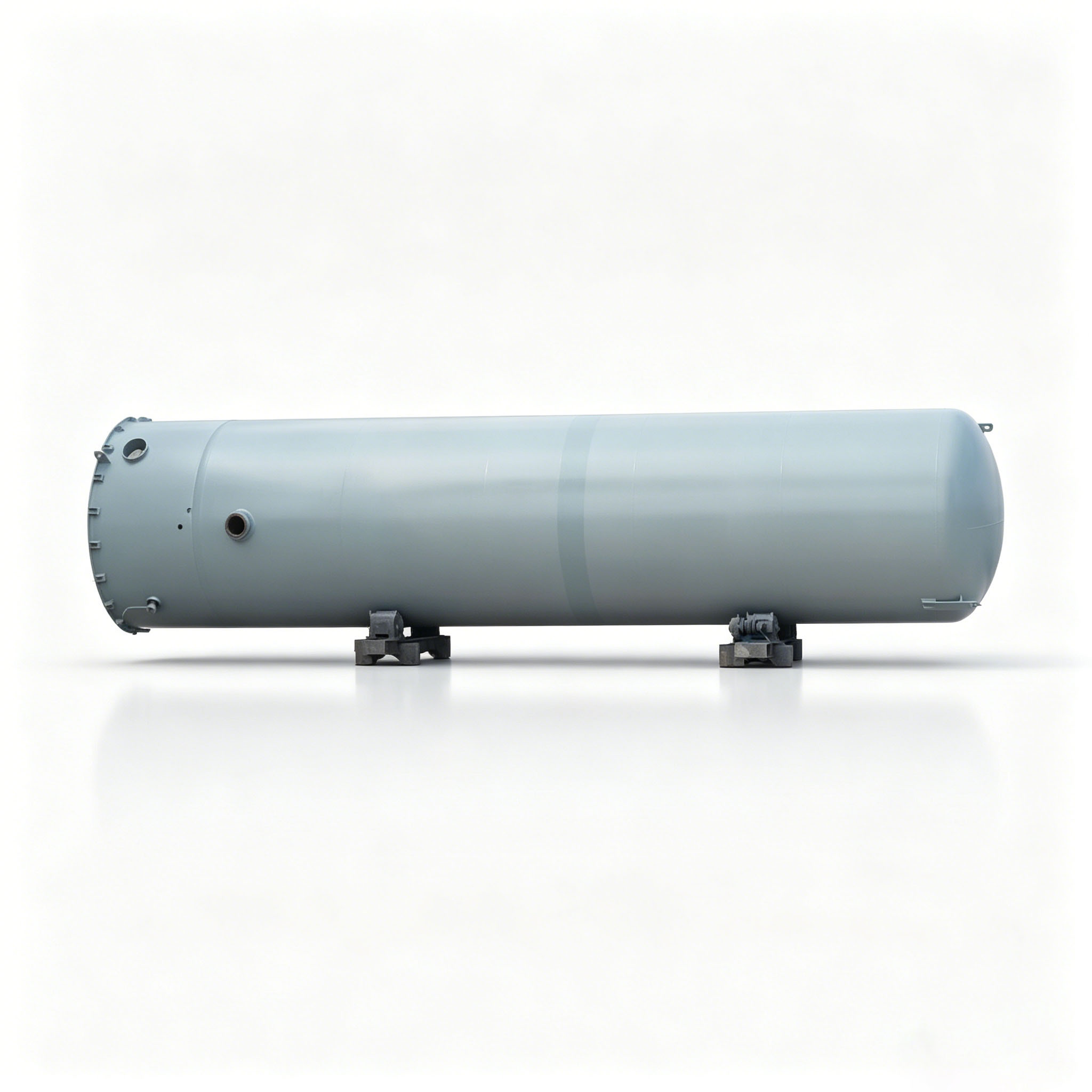
The storage tank substrate of the equipment under test is conductive, while the internal layer is covered with an insulating protective coating (such as epoxy, PE, rubber lining, cable sheath, enamel, etc.). The detector outputs high-voltage DC or pulse current to a scanning probe. When the metal substrate is reliably grounded, a complete circuit is formed.
- Intact Coating: The insulation completely blocks the high voltage → No electrical discharge, no alarm.
- Through-Film Defects (Pinholes, Cracks, Thin Spots, Exposed Metal): The high voltage breaks down the air gap at the defect → Visual electric sparks are generated, and the instrument triggers an audio-visual alarm to precisely locate the leakage point (commonly referred to in the industry as a Holiday).
2. Standardized Testing Steps
2.1 Pre-testing Preparation
- Surface Pretreatment:
- Clear the coating surface of dust, oil, accumulated water, and loose paint.
- Note: For damp surfaces, a pulse-type detector is preferred to prevent DC charge accumulation from causing false alarms.
- Focus grinding and cleaning efforts on vulnerable areas such as welds, corners, flanges, and joint coatings.
- Circuit Grounding:
- Securely clamp the ground wire to bare metal, ensuring minimal grounding resistance. Failure to establish a proper circuit will result in missed defects.
- Voltage Setting & Calibration (Critical Step):
- Calculate the nominal test voltage based on coating thickness (T), material type, and applicable standards.
- Thin Coatings (≤ 1 mm): Calculate using the general formula: V = K sqrt T, where V is the voltage, T is the thickness mm, and K is the material coefficient (Epoxy: 3300, Polyethylene: 7840, Rubber: 4000).
- Thick Coatings (> 1 mm, e.g., 3PE, Rubber Lining): Set a fixed voltage according to national standards or engineering specifications (e.g., 3PE ≥ 25kV, Rubber Lining: 8 ~ 20kV, FBE Epoxy Powder: 5kV).
- Caution: Excessively high voltage will puncture intact coatings, causing secondary damage; excessively low voltage will fail to detect minute pinholes.
- Probe Selection:
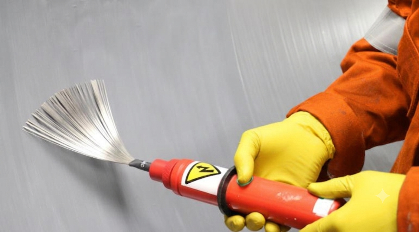
- Large Flat Surfaces: Use conductive brass brushes or rolling conductive rubber/sponge electrodes.
- Welds / Pipes / Arcs: Use coiled spring electrodes or flexible brass wire probes.
- Tight Corners & Blind Spots: Use fine metal needle probes.
2.2 On-site Scanning
- Keep the probe in close contact with the coating surface and move at a uniform speed ($\le 0.3\text{ m/s}$). Moving too fast highly increases the risk of missing micro-defects.
- Scanning Sequence: Scan corners, welds, overlaps, and joint coatings first, followed by large flat areas. Ensure full coverage without gaps or random skipping.
- Low-ambient-light environments are preferred for easier visual tracking of the blue electric sparks. When the probe passes over a defect, “Sparking + Buzzing + Flashing Indicator” occur simultaneously.
- Once an alarm is triggered, mark the location immediately. Slowly move the probe back and forth over the spot to rule out temporary false alarms caused by static electricity or surface moisture.
- After scanning the entire surface, re-test and confirm all marked defect areas.
2.3 Defect Repair & Re-testing
- Grind, clean, and re-apply the protective coating to all non-compliant holiday locations.
- Once the patch has fully cured and cooled, perform a 100% spark re-test on the entire repaired zone until no alarms occur.
2.4 Documentation & Archiving
- Record the instrument model, calibration date, set voltage, coating thickness, scanning speed, number and locations of defects, repair/re-test results, and the operator’s name.
3. Acceptance Criteria (All conditions must be met)
| Evaluation Dimension | Acceptance Standard |
| 1. Zero Discharge Alarm (Core Index) | When fully scanning the coating surface at the specified test voltage: • Zero visual electric sparks. • Zero buzzer or fault alarm light triggers. • Zero instantaneous discharge pulse signal outputs. |
| 2. Defect Density Limits | Allowable holiday densities vary by industry standard: 1) Oil & Gas Pipelines (3PE/FBE): Strictly 0 holidays; no penetration pinholes allowed. 2) Rubber Linings (GB 18241.1): 0 through-defects per square meter. 3) Standard Epoxy Floors / Small Steel Structures: Some projects allow ≤ 1 micro-defect per 10 Square Meters, provided it is repaired and passes re-testing. 4) Cable Sheath Online Testing: Zero breakdown sparks per unit length. |
| 3. Parameter Compliance | • Instrument must be calibrated with a voltage output error ≤ 5%. • Scanning speed ≤ 0.3m/s ; environmental humidity ≤75%. • Test voltage must not fall below the minimum specified code, nor exceed the upper limit that could damage the coating. |
| 4. Thickness Uniformity | Cross-verify with a coating thickness gauge: local thickness must not fall below the lower design limit to eliminate latent risks where insulation is insufficient despite no spark breakdown occurring. |
4. Rejection Criteria (Any single violation results in rejection)
- Presence of Penetrative Spark Discharge: Any continuous or instantaneous blue electric spark between the probe and the substrate, accompanied by an audio-visual alarm, indicates a through-film defect (e.g., pinholes, sandholes, ruptured blisters, coating cracks, missed weld coatings, exposed metal from impacts, or severely insufficient local thickness).
- Excessive Defect Density: The number of holidays per unit area exceeds the allowable limit of the standard. Even if individual repairs are possible, the entire coating process must be evaluated for systemic failure, which may require full stripping and recoating.
- Persistent Discharge (Excluding False Alarms):
- False Alarms: Caused by surface water accumulation, dust static, or edge/tip corona. These disappear after wiping dry and cleaning.
- True Defects: Stable electrical discharge concentrated at a single exact point during multiple repeated tests → Judged as unqualified.
- Non-compliant Test Parameters:
- Voltage set below standard requirements (renders the current inspection invalid; must increase voltage and re-test).
- Grounding failure or excessive scanning speed (high risk of missed areas; renders the test void).
- Re-testing Failure After Repair: If a spark discharge occurs again in the same area or at the edge of the patch during re-testing after the repair has cured, the repair is judged as failed, and the coating must be thoroughly removed and re-applied.
5. Common Reference Standards
- Buried Steel Pipelines Coating:
SY/T 0063,SY/T 0447,ISO 21809-3 - Tank / Equipment Rubber Lining:
GB 18241.1,ASTM D3486 - Cable Insulation Sheath:
GB/T 2952,IEC Spark Test Standards - General Anti-corrosion Linings: Applicable to epoxy resin, enamel, fiberglass reinforced plastics (FRP), and other lined equipment.