An All-Dimensional Guide to Liquefied Petroleum Gas (LPG) Residual Liquid Storage Tanks: Operational Architecture, Technical Standards, and Closed-Loop Management
1. Sources of LPG Residual Liquids and Operational Vulnerabilities of Non-Dedicated Storage
1.1 Primary Breakdown of Residual Liquid Generation
In modern Liquefied Petroleum Gas (LPG) station operations, residual liquids represent an inevitable byproduct generated across diverse operational stages. These fluids predominantly originate from four critical industrial activities:
- Cylinder Residual Evacuation: The systematic recovery of heavy hydrocarbon fractions remaining in end-user cylinders prior to refilling.
- Unloading and Charging Purges: Media discharges and systematic nitrogen or vapor replacements executed during tank truck unloading and cylinder filling procedures.
- Maintenance Protocols: Decompression, component drainage, and system line-purging conducted during routine equipment maintenance or switching between operational states.
- Manifold and Pipeline Venting: Standard depressurization operations across valve manifolds and product transfer pipelines to ensure system integrity.
1.2 Operational Vulnerabilities and Hazards of Temporary Storage
The absence of dedicated, permanently installed residual liquid storage equipment forces stations to rely on fragmented, temporary containers. This makeshift approach compromises safety and efficiency, introducing severe operational risks:
- Management Fragmentation: Dispersed storage creates significant obstacles for rigorous inventory ledger maintenance and real-time on-site tracking.
- Environmental and Fugitive Emissions: Fragmented configurations frequently suffer from minor leaks, structural weeping, and the escape of volatile, pungent mercaptan odors, which compromise local air quality.
- Elevated Fire Hazards: The unregulated accumulation of highly flammable, pressurized media across the facility creates an unpredictable, continuous fire and explosion hazard.
1.3 Core Engineering Value of Dedicated Storage Tanks
By implementing fixed-configuration LPG residual liquid storage tanks equipped with standardized process interfaces, facility operators establish a closed-loop system for collection, temporary holding, and bulk transport. This technological integration transforms site management from a reactive posture to a standardized, highly regulated routine. Ultimately, it mitigates operational uncertainties and eliminates safety hazards at their source.
2. Deployment Topographies and Spatial Layout Regulations
2.1 Mainstream Application Scenarios
Dedicated residual liquid storage systems serve as critical infrastructure across several vital sectors of the LPG midstream and downstream supply chain:
- Cylinder Filling Stations: Integrated directly with automated residual evacuation manifolds to facilitate rapid, high-throughput recovery.
- Distribution and Vaporization Hubs: Positioned as the central terminal for valve group venting and pipeline depressurization networks.
- Bulk Storage and Transfer Terminals: Serving as the dedicated receptor for large-scale equipment maintenance drains and media replacement purges.
2.2 Spatial Layout and Siting Regulations
The positioning of the residual liquid storage vessel within a facility must balance operational efficiency with rigorous regulatory compliance. The vessel should be located close to primary collection points, pump houses, or central valve manifolds. This minimizes pipeline distance, reduces frictional pressure drop, and optimizes pump suction heads during liquid transfer.
Concurrently, the layout must provide ample clearance for maintenance access, heavy lifting equipment, and transport vehicle positioning. Most importantly, it must strictly comply with statutory fire separation distances from adjacent hazards. By optimizing these factors, the storage tank functions as the operational anchor for centralized containment and unified transport processing.
3. Structural Configurations and Process Interface Architecture
3.1 Selection of Mainstream Structural Forms
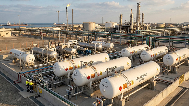
Horizontal vessel configurations represent the industry standard for LPG residual liquid storage. This preference stems from mature manufacturing processes, excellent structural stability, and ease of factory prefabrication. Furthermore, horizontal tanks simplify long-distance transport, crane rigging, and field installation, making them highly adaptable to varied site topographies.
Architecturally, a standard horizontal vessel comprises a cylindrical shell, two elliptical or torispherical dished heads, load-bearing saddle supports, and an array of specialized process nozzles welded to the shell.
3.2 Standard Process Interface Matrix
To facilitate seamless fluid dynamics during collection and evacuation, the nozzle configuration must follow strict functional layouts. The typical interface matrix includes:
| Nozzle Designation | Primary Engineering Function | Typical Orientation |
|---|---|---|
| Liquid Inlet Port | Receives gravity-fed or pump-assisted residual liquids from various site collection points. | Top Shell |
| Liquid Discharge Outlet | Connects to transfer pumps for bulk evacuation, transport vehicle loading, or downstream treatment. | Bottom / Lower Shell |
| Vapor Return / Vent Port | Balances internal pressure during fluid transfer and connects to the flare or vapor balance line. | Top Shell |
| Drain / Clean-out Port | Facilitates complete evacuation of heavy ends, water, and particulate sludge during maintenance. | Lowest Point of Head/Shell |
| Instrumentation Interfaces | Dedicated ports for continuous hydrostatic/radar level transmitters and pressure monitoring gauges. | Top / Side Shell |
3.3 Pre-Execution Layout Optimization
Because residual liquid networks involve multi-point collection and intermittent, high-velocity pump evacuation, upfront engineering layout is vital. Confirming exact nozzle orientations and the layout of associated valve manifolds during the initial design phase reduces field pipeline modifications. This proactive step accelerates mechanical completion and shortens the commissioning schedule.
4. Equipment Selection Framework and Technical Data Requirements
Selecting an LPG residual liquid storage tank requires matching its parameters to the site’s generation profile and downstream treatment capacity. Standard commercial specifications should not be used without custom verification.
4.1 Site-Specific Operational Variables
Design teams must analyze several distinct operational factors before sizing the vessel:
- The chemical composition and specific gravity variations of the incoming residual streams.
- The peak and average volumetric generation rates, which dictate the necessary operational buffering volume.
- The motive fluid dynamics, evaluating whether the system relies on gravity flow, differential gas pressure, or mechanical pumping.
- Direct integration links with downstream processing units, such as fractionating columns or heavy-end incinerators.
- Physical plot limits and structural loading restrictions of the installation site.
4.2 Mandatory Baseline Data for Procurement Inquiries
To secure accurate commercial quotations and robust engineering designs, project owners must supply a comprehensive technical dataset during the formal inquiry phase. This preventative documentation ensures precise sizing of the vessel volume, optimization of nozzle schedules, and appropriate selection of auxiliary trim:
- Volumetric Quantification: Total calculated residual liquid yield and its distribution across different on-site sources.
- Downstream Logistics: The planned operational cycle for liquid evacuation and the handling methods used by transport vehicles or disposal facilities.
- Process Flow Integration: Complete master Process Flow Diagrams (PFDs) of the facility.
- Site Conditions: Detailed geotechnical profiles, civil foundation parameters, and tie-in points for existing utility piping.
5. Field Civil Engineering and Construction Requirements
LPG residual liquid storage vessels are typically installed above ground. This configuration requires a coordinated construction plan that integrates civil foundations, plot layout, and interconnecting pipe racks.
- Civil Foundations: Foundations must be engineered based on the vessel’s dry weight, maximum liquid payload, hydrostatic test loads, and local seismic or wind factors. The design must provide clear maintenance clearance around the saddles and provide dedicated support structures for accompanying valve skids, while strictly maintaining safety separation distances.
- Corrosion Mitigation and Coating Systems: External coating systems must withstand local atmospheric corrosivity categories (per ISO 12944). For coastal installations with high humidity or industrial areas with high chemical exposure, the design specifications must define surface preparation standards (e.g., Sa 2.5), dry film thickness (DFT) metrics, and strict quality acceptance criteria. These measures prevent premature structural degradation.
- Upfront Systems Integration: Comprehensive, upfront coordination of structural interfaces, valve arrangements, and pipeline routing during the initial engineering phase ensures smooth field construction. This detailed planning prevents interferences and supports efficient facility commissioning.
6. Manufacturing Codes, Standards, and Quality Assurance Protocols
As definitive pressure vessels containing hazardous materials, LPG residual liquid storage tanks must comply with strict statutory manufacturing standards, such as ASME Section VIII, EN 13445, or GB 150.
6.1 Critical Quality Control Benchmarks
During factory fabrication, quality control inspectors must focus on four critical areas:
- Material Traceability: Verifying mill test certificates and chemical/mechanical properties of pressure-retaining steel plates and forgings.
- Welding Excellence: Monitoring weld preparation, qualifying welding procedures (WPS), testing welder performance (WPQR), and controlling interpass temperatures.
- Geometric Accuracy: Verifying shell roundness, alignment tolerances, and nozzle positioning accuracy.
- Sealing Integrity: Inspecting gasket seating surfaces and ensuring precise machining of flange faces.
6.2 Non-Destructive Examination (NDE) and Proof Testing
All pressure-retaining welds must undergo Non-Destructive Examination, including Radiographic Testing (RT) or Ultrasonic Testing (UT), supplemented by Magnetic Particle (MT) or Dye Penetrant (PT) inspections. Following NDE approval, the completed vessel must undergo a hydrostatic test at design-specified overpressure, followed by a rigorous pneumatic tightness test to verify zero-leakage performance before factory sign-off.
6.3 Final Pre-Shipping Inspection and Order Alignment
Before shipment, inspectors must perform a final check to confirm nozzle orientations, verify nameplate details, and check the presence of all ordered accessories. Aligning interface configurations, ancillary component delivery scopes, and final quality documentation during contract execution simplifies site receiving inspections and accelerates project sign-off.
7. Customization Boundaries and Commissioning Services
7.1 Scope of Bespoke Engineering Customization
Equipment manufacturers provide extensively tailored vessel packages to match unique site requirements. Customization options encompass volumetric capacities, personalized nozzle schedules, optimized layout configurations for valve skids, and heavy-duty, multi-layered coating systems. For automated facilities, vessels can feature integrated guided-wave radar transmitters, continuous gas leak detection arrays, and automated emergency shutdown valves (ESV) tied directly to the facility’s safety instrumented system.
7.2 Logistics, Handover, and Site Support Services
Vessels are shipped as fully assembled units or split modules, depending on overall dimensions and transport clearance restrictions. Handover services extend beyond transport delivery; manufacturers provide field engineering support, including piping tie-in alignment advice and comprehensive technical briefings. This technical support helps minimize construction errors and supports rapid, safe commissioning.
8. Strategic Operational Conclusion
Implementing standardized residual liquid management directly reflects an LPG facility’s operational safety and regulatory compliance. By deploying dedicated LPG residual liquid storage tanks, operators establish a reliable “Centralized Collection — Compliant Storage — Unified Evacuation” lifecycle protocol. This system replaces hazardous temporary storage practices, eliminates fugitive emissions, and provides robust, long-term infrastructure to support successful safety audits and sustainable facility operations.